Condition monitoring in electric motor drives is essential for operation continuity. Statistical methods are used to detect all types of machine faults, including bearing, BRB, stator winding, demagnetization, etc. Mathematical analysis, simulations, and simple experiments provide enough information to build these FDD systems. ML methods are becoming more popular to detect all types of faults but the availability of data is the key. In contrast, deep-learning methods require much more data than ML methods and their applications are mostly to detect bearing faults. On the power electronics side, device physics is exploited, as well as topology and modulation, to detect faults. The abrupt nature of power electronics faults pushed researchers to logic-based methods which are, in general, faster and application specific. Model-based approaches are also fast and can be applied to different scenarios.
- motor drives
- condition monitoring
- fault detection and diagnosis
- fault mechanism
- power electronics
- power electronics faults
- machine faults
1. Introduction
Electric motors are the powerhouse of the industry with applications ranging from manufacturing to transportation. With the rise of electric vehicles (EVs) and the push for electrification, their usage is increasing. Keeping motors and their drives healthy is crucial to maintain operation continuity or service uptime. However, due to environmental conditions, regular wear and tear, installation and manufacturing defects, or overloading, electric motor drives are subject to failures. These failures can be on the motor side or the power electronics side. Detection of these faults is an indispensable function for operation safety, fault tolerance, mission completion, or fast maintenance.
In the literature, there are several fault detection and diagnosis (FDD) review articles for electric machines and drives. It is possible to find review articles ranging from widely inclusive to narrowly focused ones. The focus of these reviews can be certain fault types such as stator faults [1], bearing faults [2], or sensor faults [3]. Other reviews focus on specific FDD methods such as machine learning (ML) [4,5], deep learning (DL) [6], or finite element analysis [7]. The focus can also be a certain type of motor or drive topology, for example, induction motors (IM) [8], permanent magnet motors [9], or multilevel inverters [10]. For established researchers in a field, narrowly focused reviews might be more practical as they touch on topics in greater detail. These reviews are looking to detect a specific fault in a specific machine using a predefined method. Some examples are [11,12]; wherein [12], articles detecting broken rotor bar faults are looked at for IMs, utilizing fault-signature analysis. Similarly, in [11], bearing fault detection studies in IMs using deep-learning methods are collected. These reviews provide indepth insight into their focus area.
Presenting the latest research with accessible tables is also important. Some reviews lack these tables for fast referencing [13]. Another point is fault mechanisms are not necessarily provided in all review articles. Thus, the existing literature may not be suitable for a researcher trying to get into this field or someone who needs a broad review of condition monitoring in IM drives.
Our aim with this review article is to show possible faults in motors and other drive components, explain their mechanisms in brief, and provide potential approaches to detect and diagnose these faults. We aim to present a big picture without missing the essence of each component.
1.1. Methodology
In this review, drive faults are addressed as four categories: machine faults, power electronics faults, DC link capacitor faults, and sensor faults. Condition monitoring methods for machine FDD are divided into statistical methods, ML-based methods, and DL-based methods. Though ML- and DL-based methods contain similar preprocessing stages to statistical methods, they are treated as separate categories due to their difference in later modeling stages where neural networks (NN) are employed. We realized the categorization of some of the methods is not always straightforward and might be harder to put them into one category. We used our judgement to categorize them as shown in Figure 1.
Power electronics FDD methods are divided into logic-based, residual-based, and controller-aided methods. Logic-based methods do not require a model of the system to detect failures but may utilize a model or an actual drive to determine signal thresholds. Residual-based methods require a system model. Controller-aided methods also use system models but these models are used for control as well; there is no need for an additional FDD model of the system. Sensor and DC link capacitor FDD are briefly explained and critical points and overlaps with other methods are given. The categorization process is depicted in Figure 1.
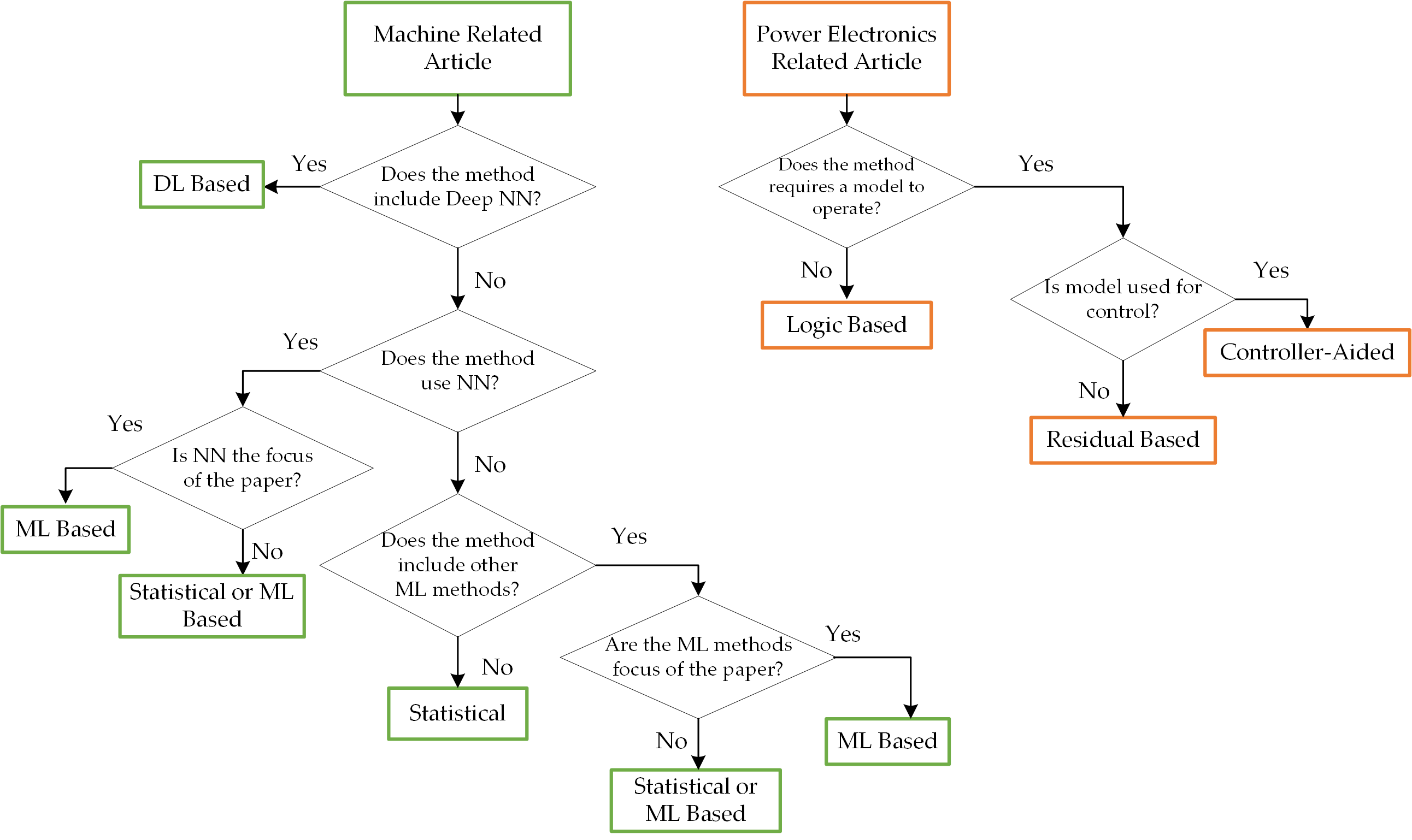
Figure 1. Flowchart of FDD-method categorization.
Machine FDD methods are summarized and compared in Tables 1–3 for each of the previously classified categories. Also, some of the common open-source data repositories
containing machines and drives related data are listed in Table 4 for interested readers. Power electronics faults are presented in Table 5.
Most citations are from the last five years but some critical references are added regardless of their publication years. Also, when selecting prior work, we tried to give equal weight to different approaches. For example, to detect bearing faults, vibration signals are used mainly, and there is more literature on detection using vibration signals. However, we included studies that make use of flux, speed, or current signals.
The paper is organized as follows: Section II explains possible fault modes in different parts of a typical motor drive, and briefly explains their manifestation. 3–6 explain the FDD methods for machines, power electronics, sensors, and DC link capacitors, respectively. Section 7 concludes the paper by comparing FDD approaches, pointing out the challenges and providing insights into potential research areas.
2. Fault Space
2.1. Drive Topology
A motor drive system consists of a motor, power electronic converters, sensors, and a controller unit, as shown in Figure 2. Apart from the main DC–AC inverter, based on the energy source, the drive may contain DC–DC converters if it is fed from a battery or AC–DC rectifiers if supplied by an AC source. The industry standard for the DC–AC inverter is accepted to be three-phase two-level inverters. If not mentioned specifically, such as multilevel inverters, this topology is considered throughout the article. Multiphase drives beyond three-phase are out of the scope of our paper.
Any damage or failure to these components poses the risk of a complete system breakdown. Some parts of the drive are more susceptible to failure than others. Reliability analyses for motor drives are conducted for different applications, such as battery EVs [14,15]. These studies show that, for EV applications, the motor controller (including sensors) has chances of failing when compared to the motor itself. Within the power electronics unit, gate drivers and IGBTs have the highest chance of failure. Among the components of the motor, bearings, rotor bars, and stator windings exhibit the highest failure rates and cover most of the fault space. Speed transducer failures are also significant. These results match with the EPRI study and IEEE study on motor-failure causes [16]. These studies show that bearings, broken rotor bars, and stator winding short-circuit failures correspond to more than 75% of the faults.
To keep this review focused, the most common failures will be considered. For motor faults, bearing-, stator- and rotor-related faults will be discussed. For power electronics faults, power semiconductor device failures will be discussed. Sensor faults will be considered with emphasis on speed sensors and current sensors. Lastly, DC link capacitor failures will be discussed.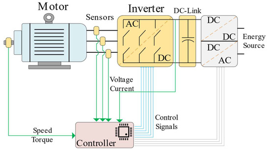
2.2. Machine Faults
2.2.1. Bearing Faults
2.2.2. Stator- and Rotor-Related Faults
The stator and rotor are the main parts of a machine. The stator has windings and insulation material between turns and slots. Whereas the rotor can be wound, a squirrel cage, or can contain permanent magnets. A properly installed motor should have a balanced rotor with a constant air gap between the stator and the rotor.
The most common failure for the stator is interturn short circuits or interturn failures. These failures evolve into phase-to-phase or phase-to-ground failures [20]. The reasons for these short circuits are mechanical and thermal stress on insulation materials leading to their eventual breakdown [21]. They create a sideband frequency on phase currents [22].
In squirrel-cage rotors, broken rotor bars and cracked end rings are common rotor faults [23]. Due to thermal stresses during turn-on transients or mechanical vibrations stemming from load changes, one or more rotor bars can be broken. Broken bars lead to imbalanced rotor currents which create uneven heating and accelerate aging [12].
Another set of fault types is eccentricity faults which change the generation of flux within the machine due to varying airgap. There are three main types of eccentricity faults: static, dynamic, and mixed, as illustrated in Figure 3. In the case of static eccentricity, the center of the stator and the center of the rotor are not perfectly aligned. As a result, the rotor rotates at a different location compared to the center of the stator, although the rotational center remains the same as the rotor’s center. On the other hand, dynamic eccentricity occurs when the center of rotation aligns with the center of the stator but the center of the rotor is not aligned with the other two centers. Mixed eccentricity exhibits characteristics of both static and dynamic eccentricities, with all three centers (stator, rotor, and rotation) being misaligned. The misalignment of the rotating center modifies the generated flux. In effect, this flux will create sideband frequencies in the stator currents [8]. The generated flux pattern differs in each type of eccentricity fault.
Demagnetization failure is another common fault specific to permanent magnet motors. It occurs due to high loading conditions or temperature stress, depending on the magnet type. The inverse magnetic field generated by the stator can demagnetize the core. Core demagnetization can be complete and, hence, affects the whole core, or can be partial. A demagnetized core will cause harmonics, noise, and vibration [24].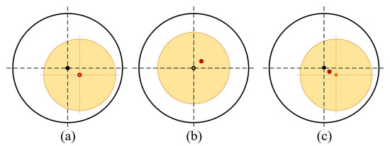
2.3. Power Electronics Faults
In motor drive systems, power electronics inverters act as the actuators for the motor. They generate the required voltage and current to achieve the required torque or speed references. Although inverter topologies may vary by application, fault models and their manifestations are similar. Failed power devices within inverters can act as open circuits where there is no gate response and the switch is open or as short circuits where they act as a low-impedance path. These two faults are similar for all types of switches, such as Si, SiC, or GaN-based MOSFETs or IGBTs.
Although the manifestation of faults is the same, their mechanisms vary with the material. Si and SiC have similar fault mechanisms; however, fault mechanisms for GaN devices are different. Fault mechanisms can be divided into two parts: intrinsic and extrinsic faults. Extrinsic faults are tied to the packaging of the devices. They happen due to different thermal reactions within the layered structure of the package. These include bond-wire fatigue, restructure of metallization, and solder-joint fatigue. Intrinsic failures happen within the semiconductor die and are related to the physical properties of the device [25,26]. Dielectric breakdown and hot carrier injection are examples of such failure mechanisms. The extrinsic failure mechanisms for GaN are reported to be similar to the Si counterparts but intrinsic failure mechanisms, such as delamination, are different [27–29].
2.4. Sensor Faults
In motor drive systems, sensor feedback is essential for control, estimation, and condition monitoring. There are three main sensors in a motor drive system, namely voltage, current, and speed sensors, except in speed-sensorless drives. All these sensors can fail at any point and with different failure mechanisms. These include temperature drift, increased noise, increased variance, bias, or zero output. Sensors are made from different materials and with different properties, e.g., current transformers to optical sensors. Each type of sensor has a different fault mechanism.
2.5. DC Link Capacitor Fault
For motor drives to maintain stability during transients, the power electronic inverter is interfaced with a DC link capacitor which responds to instantaneous high current demands. Due to their electrochemical nature, capacitors are likely to age. According to industrial surveys for EVs and motor drive applications, capacitors have the highest susceptibility to failures, second to semiconductors [30].
Capacitor aging is reflected as reduced capacity and increased equivalent series resistance (ESR). Subject to high temperatures, power cycling, and other environmental conditions, capacitors start to degrade and eventually fail [31].
3. Fault Detection and Diagnosis in Electric Machines
In motor drive systems, various signals can be captured and employed for fault detection and diagnosis (FDD). Common signals obtained from the motor side include phase currents, terminal voltages, DC link voltage, vibration, temperature, speed, torque, and flux around the machine. Additionally, signals within the controller unit, such as reference voltage or currents, gating patterns, etc., can be employed.
For FDD, different studies and applications make use of some of these signals in various ways. The utilization and processing of these signals vary between studies and applications. These quantities may be used directly or processed before being utilized.
Various fault-detection techniques can be employed to address the faults discussed in Section II-A. These techniques can be further categorized based on the data handling methodology employed. Despite the use of similar signals or measurements, distinct approaches are employed in detecting failures in each study. The techniques used can be classified into three main categories:
- Statistical Methods;
- Machine-Learning (ML)-Based Methods;
- Deep-Learning (DL)-Based Methods.
It is worth noting that the categorization of the methods is not always straightforward; some methods may fall into multiple categories while others may not fit into any of these categories. For example, in [17], the authors used wavelet transform on vibration signals to feed this information to a convolutional neural network (CNN) which falls into categories 1 and 3. In [32], graph theory is used and merged with k-nearest neighbor methods (kNN), which makes it hard to categorize. The categorization process is shown in Figure 1.
These methods can be generalized, as shown in Figure 4. Data for these three categories can be collected from experiments, simulations, or data repositories. These data include healthy and various faulty conditions. Later, based on the adopted method, fault detection is performed.
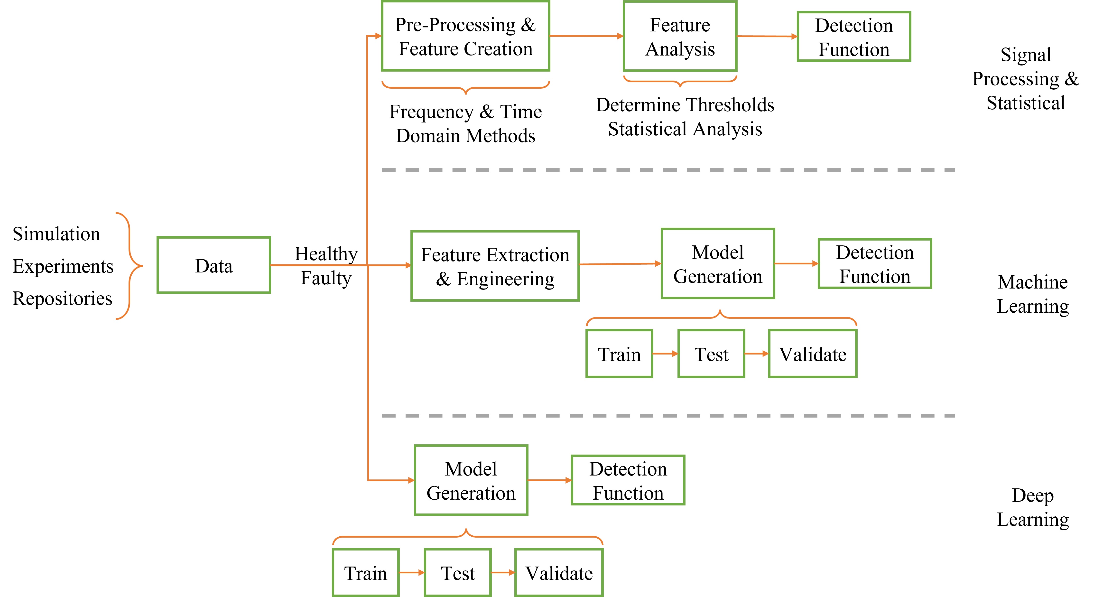
Figure 4. Block diagrams representing general operating principles of FDD methods.
Detection can also be done in various ways. Three of the common ones are illustrated in Figure 5. Model-based or regression-based methods use certain thresholds for fault detection. All statistical methods and some ML methods also use this approach. The second detection method is using classification, which is used by ML and some DL methods. In detection by classification, each new sample is classified as healthy or as one type of fault. The third detection method is detection by NNs, which is used by some ML and DL methods. NNs are trained to give direct health information so no additional detection block is needed.
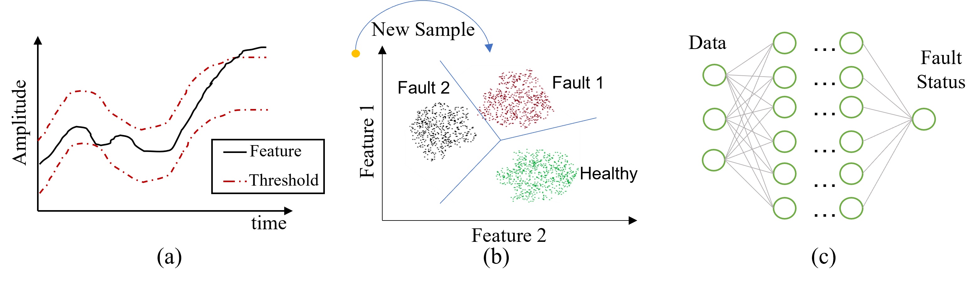
Figure 5. Detection methods, (a) Threshold based, (b) Classification based, (c) NN based.
3.1. Statistical Approaches
Statistical methods employ signal-processing techniques to analyze data in time, frequency, or time-frequency domains. In the time domain, RMS and residual analyses are often employed. In the frequency domain, the FFT and wavelet transform, or other statistical approaches like skewness, kurtosis, and special distributions are employed. Many of these utilize direct measurements, so results are easy to interpret and easy to implement for online cases. However, recent studies revolve around ML approaches and the trend is shifting from statistical methods to ML methods as more and more data becomes available.
3.1.1. Bearing Faults
To detect bearing faults, the most commonly used signal is vibration [11,17,18,32–39]. Researchers also considered using speed measurement [40], current measurements [41], flux measurement [35], and thermal images of the motor [42]. Bearing faults are common for all types of motors including induction motors (IM), permanent magnet synchronous motors (PMSM), and brushless DC motors (BLDC).
A model-based detection method is proposed in [34] using probabilistic techniques. It is an online detection method and is suitable for time, frequency, or envelope analysis. The authors propose to use a particle filter to create the feature vector and estimate a probability mass function (PMF). If the PMF exceeds the confidence value, the fault is detected. The system is learned from the data using recursive least squares with a forgetting factor. The method allows for identification and prognosis but it is not experimentally validated. In [43], the authors used mean values and standard deviations to detect faulty operation. Researchers in [40] used a time-frequency method called variational mode decomposition to detect failures. They utilized angle transformations to enhance detection capabilities. In [11], authors used entropies and kurtosis of vibration signals to detect failures. Later, they employed SVM to classify the fault. They incorporated experimental data and an online dataset to detect failure with varying operating conditions. Fast spectral correlation and enhanced envelope spectrums methods are investigated in [37], where the cyclic property of the bearing fault is exploited.
3.1.2. Stator and Rotor Faults
Stator interturn faults, broken motor bars, and eccentricity faults have unique signatures on the current and torque spectra [44,45].
The stator- and rotor-related faults are detected mostly using phase currents [46–56]. Utilizing the motor flux is also another approach [57–62]. Some studies used motor torque [63] and acoustic signals [64,65] as fault identifiers. The advantage of using flux signals is to detect failures in their incipient stages. Detecting early-stage failures can be difficult with current or vibration signals since there are multiple factors affecting them.
Though their stator designs are similar, the driving circuitry for IM and PMSMs are different. This creates a need for different detection schemes. Also, IM and PMSMs have different rotor structures and different types of rotor failures.
In [55], the authors proposed the motor current signature analysis (MCSA) method to detect stator inter-turn faults on IM drives using current signals. MCSA is a method that utilizes certain sideband frequencies on the line current of motors [23]. By analyzing the harmonic content of the current signal, certain faults can be detected. Reference [53]. proposes to use the square value of line currents and use multiple signal classification techniques. The squared current amplifies the fault indicators to better detect broken rotor bar faults. Apart from current signals, the authors of [60] proposed placing flux sensors to detect interturn faults in their incipient stages which is not possible to detect using classical methods. By placing three flux sensors, stray flux can be monitored to detect interturn failures in IMs utilizing harmonic analysis. Similarly, the authors in [57] used flux sensors to detect broken rotor-bar failures using a flux spectrum where MCSA is not applicable. In [58], flux sensors are placed inside the airgap to capture real-time flux data which enabled fast detection of eccentricity and rotor failures. PMSM and BLDC motor stator failures can be detected with their current and flux signals. The authors of [47] investigated the usability of current signals to detect failures on a six-step voltage source-driven BLDC. They discovered that the third harmonic is the best feature to detect stator failures. In [61], the third harmonic of the flux signal is also utilized to detect interturn short-circuit faults as well as their locations. In [48], vibration signals are used on top of the current signals. They utilized a spectral analysis method called Fast Kurtogram on the vibration signals which proved to be very accurate for severe faults. In the incipient stage, they employed MCSA and looked at the third harmonics of the current. Ref. [59] uses fluxes to detect both rotor eccentricity and demagnetization faults, which cause flux asymmetry. Residual analysis is done to differentiate demagnetization from eccentricity.
Partial demagnetization is taken into consideration in [56]. Certain harmonic orders are extracted and an envelope is created to detect faults. A faster and more precise detection of the demagnetization fault is possible by installing fluxgate sensors, as suggested in [62], which gives the ability to detect faults in incipient stages.
3.2. ML-Based Methods
ML is a broad category that includes logistic regression, support vector machines (SVM), decision trees, and neural NN. Fuzzy methods can also be considered in the ML methods. ML methods require feature engineering for high-performance operation or satisfactory accuracies. They do require training and testing which needs prior data to operate.
3.2.1. Bearing Faults
The authors in [18] used statistical time features of vibration signals as well as compressed features to make them interpretable. A hierarchical NN is then trained and used for classification. Detection is done by classification where the classifier chooses between healthy and multiple faulty states. The researchers in [33] utilized autocorrelation information and extracted features from autocorrelations rather than the raw data itself. Then, a random-forest classifier is used to classify the healthy state from different faulty states. The authors in [39] used an NN-based filter for vibration signals and then fed the features to a second NN with a multilayer perceptron (MLP) structure. It is shown that, with the addition of the filter, the detection and classification accuracy increased dramatically. Apart from using NNs, ensemble classifiers such as random forest and XGBoost can also be used. In [66], phase-current signals are processed using discrete wavelet transform and different ensemble classifiers are tested. This method achieved 99% accuracy for fault detection with XGBoost. Thermal images were also used to detect bearing faults [42] and have the advantage of being nonintrusive and noncontact. Collected images are used as 2D signals and 2D wavelet transform is applied to images to generate features. The dimensionality reduction technique, namely principal-component analysis, is applied to the feature set to pick the best features. The authors reached 100% accuracy in detection and classification using the SVM classifier.
Table 1: Summary of Machine FDD using Statistical Methods.
|
Method |
Analysis Type |
MT 1 |
Fault Type |
Used Signals |
Fault Indicator |
Svrty? 7 |
Ref. |
|
|
Improved Dynamic System Model with Particle Filtering |
St 2 |
- |
Bearing |
Vibration |
Deviation from healthy operation based on healthy model |
No |
[35] |
|
|
Complementary Ensemble Empirical Mode Decomposition, Weighted Multiscale Entropy |
St 2 |
IM |
Bearing |
Vibration |
Refined Composite Multiscale RMS (RCRMS), Kurtosis |
Yes |
[36] |
|
|
Sparse Code Shrinkage Denoising, Fast Spectral Correlation |
Frq 3 |
- |
Bearing |
Vibration |
Ball pass frequency |
No |
[38] |
|
|
Angle Domain Conversion, Variational Mode Decomposition |
Frq 3 |
- |
Bearing |
Vibration, Speed |
Recurring frequency components in angle domain |
No |
[40] |
|
|
Basic Statistics |
St 2 |
IM |
Bearing |
Stray Flux |
Mean value difference in stary flux measurements |
Yes |
[43] |
|
|
Fourier Analysis |
Frq 3 |
BLDC |
Stator IT 4 |
Current |
The third harmonic in negative frequency |
Yes |
[47] |
|
|
Current Harmonic Analysis |
Frq 3 |
PMSM |
DeMgt 5 |
Current |
Amplitude of certain harmonic orders |
No |
[48] |
|
|
Motor Current Signature Analysis |
Frq 3 |
BLDC |
Stator IT 4 |
Vibration, Current |
The third harmonic in current spectrum |
Yes |
[49] |
|
|
MUSIC |
Frq 3 |
IM |
BRB |
Current |
Double multiples of slip frequency in Fourier analysis |
Yes |
[54] |
|
|
Multiple Reference Frames, MCSA |
Frq 3 |
IM |
Stator IT 4 |
Current |
The third harmonic in current spectrum |
Yes |
[56] |
|
|
Fourier Analysis |
Frq 3 |
IM |
BRB |
Stray Flux |
Increased amplitude on flux spectrum at |
Yes |
[57] |
|
|
Sensor Measurement Difference |
Time |
IM |
BRB, Ecc 6 |
Internal Flux |
Difference in airgap flux densities in similar poles |
Yes |
[58] |
|
|
Sensor Measurement Difference |
Time |
PMSM |
Ecc 6, DeMgt 5 |
Flux |
Normalized changes in flux measurements |
Yes |
[59] |
|
|
Flux Vector Analysis |
Frq 3 |
IM |
Stator IT 4 |
Flux |
Amplitude increments of frequency in Flux Vector FFT |
Yes |
[60] |
|
|
Stray Flux Analysis |
Frq 3 |
PMSM |
Stator IT 4 |
Flux |
3rd harmonic of stray flux |
Yes |
[61] |
|
|
Flux Spectrum Analysis |
Frq 3 |
PMSM |
DeMgt 5 |
Leakage Flux |
Amplitude of certain harmonic orders |
Yes |
[62] |
1 MT: Machine Type, 2 St: Statistical, 3 Frq: Frequency, 4 IT: Interturn, 5 DeMgt: Demagnetization, 6 Ecc: Eccentricity, 7 Svrty: Severity.
3.2.2. Stator and Rotor Faults
The authors in [49] used line currents to detect interturn failures in VSI-fed IMs. They extracted features with wavelet transform and later used an SVM-based algorithm. They successfully detected faults with varying switching frequencies and achieved more than 99% accuracy. Researchers in [52] used a similar approach to use line currents to both detect the stator failure and also decide the severity of the fault using two MLP models for detection and severity assignment. They also utilized a multiagent system and multiple systems to achieve generality. The detection accuracies are up to 100% for different fault cases. Utilization of torque signal to detect stator faults while deciding severity is shown in [63]. Startup torques with different severity levels are fed into an NN with one hidden layer. Accuracies ranging from 88% up to 99.9% are achieved. In [54], a broken rotor bar fault-detection scheme is proposed using ANNs by utilizing stator currents.
In [50], the authors proposed to use frequency domain features of line currents to detect stator failures on PMSMs using the kNN approach where classes are the number of shorted turns. Researchers in [51] showed that broken rotor-bar faults can be detected using current signals of PMSMs. Time-domain signals are used and statistical features are extracted. The random-forest classifier resulted in more than 98% accuracy in deciding healthy or faulty conditions. Discrete wavelet transform on the stator current is used to detect broken magnet faults and eccentricity faults in [67]. An adaptive filter is developed to remove the fundamental component of the stator current. Later, an SVM classifier is employed to classify healthy and faulty conditions.
Table 2. Summary of Machine FDD using ML Methods.
|
Method |
MT 1 |
FT 2 |
Used Signals |
FE 3 |
FS 4 |
Classifier |
Acc 5 |
Svrty? 6 |
Ref. |
|
H-MLP 14 |
IM |
Bearing |
Vibration |
STD 7, CCA 8 |
Discriminant Analysis |
H-MLP |
95% |
Yes |
[18] |
|
NN filter MLP |
IM |
Bearing |
Vibration |
TD 9 |
Removing Nonbearing Fault Component (RNFC) filter |
MLP |
96–100% |
Yes |
[33] |
|
RF |
IM |
Bearing |
Vibration |
St 10 |
Recursive Feature Elimination (RFE) |
RF 15 |
96.7–100% |
Yes |
[34] |
|
SVM |
IM |
Bearing |
Thermography |
DWT 11, St |
PCA, Mahalanobis distance (MD) |
SVM 16 |
100% |
Yes |
[42] |
|
SVM |
IM |
SIT 18 |
Stator Current |
DWT, St |
- |
SVM |
99.74% |
Yes |
[50] |
|
kNN |
PMSM |
SIT |
Stator Current |
FFT |
- |
kNN |
99.10% |
Yes |
[51] |
|
RF |
PMSM |
BRB |
Stator Current |
STD |
Feature |
RF |
98.40% |
No |
[52] |
|
MLP |
IM |
SIT |
Stator Current |
Sampled Measurement |
- |
MLP |
100% |
Yes |
[53] |
|
NN |
IM |
SIT |
Torque |
St, FD 12 |
- |
NN |
88–100% |
Yes |
[63] |
|
XGBoost |
PMSM |
Bearing |
Stator Current |
DWT, TFD 13 |
- |
XGBoost 17 |
99.30% |
Yes |
[66] |
|
SVM |
PMSM |
Ecc 19, Broken Magnet |
Stator Current |
FD |
LDA |
SVM |
96%+ |
Yes |
[67] |
3.3. DL-Based Methods
DL methods are a subset of ML methods. The main difference is that there is no feature engineering in DL approaches and they require much more data compared to ML methods. Common DL methods can be listed as autoencoders, convolutional neural networks (CNN), generative adversarial networks (GAN), recurrent neural networks, and reinforcement learning. A summary of DL methods applied for machine FDD is shown in Table 3.
3.3.1. Bearing Faults
DL-based approaches are extensively studied for bearing faults [6]. Approaches are taken to utilize autoencoder structures to denoise and detect failures [39]. Autoencoders first reduce the dimensionality of the signal and attempt to regenerate the original signal. Another approach is to convert physical signals to images and use strong image processing tools such as CNNs [17,68]. CNNs are a form of multilayer perceptron with more constraints. Also, they include convolution and pooling layers. The interpretability and performance of CNNs can also be improved by imposing physical constraints on the model; hence, physics-informed structures can be formed [37]. A different DL approach used in bearing fault detection is GAN [69]. With GAN, two parallel networks are trained to surpass the other network, hence the name adversarial. The purpose of utilizing GANs in [69] is to generate synthetic data for under-represented classes to increase generality. A promising and emerging field in fault detection using DL is deep-transfer learning and domain adaptation [11].
As mentioned earlier, DL requires a large amount of data which is hard to collect for condition-monitoring applications. Using DL to find domain-invariant features and transferring the model from one system to the other is a proposed solution for the lack of data [70].
3.3.2. Stator and Rotor Faults
For stator and rotor faults, the literature is not as rich as bearing faults due to a lack of open-source datasets. Yet, researchers have been looking into the utilization of this useful tool to achieve better results. In [71], the detection and classification of one healthy and five faulty states are investigated, including bearing faults, shorted stator windings, broken rotor bars, bent rotors, and unbalanced rotation. Authors utilized autoencoders and used generalization techniques, such as denoising autoencoder and dropout. The study shows more than 97% accuracy across the classes. Researchers in [46] focused on different levels of stator faults and they used CNN to detect and decide the severity of the fault. The paper shows accuracies for various layers and activation functions. The authors showed a single convolution layer with rectified linear unit (ReLU) activation function performs best. To increase network resistance, they added pooling layers and dropout layers which resulted in more than 99% accuracy. The authors of [72] tried to tackle the interpretability problem of DL methods by using a novel deep-SincNet structure. They used current signals to detect bearing and broken rotor-bar faults with accuracies higher than 99.9%.
Table 3. Summary of Machine FDD using DL Methods.
|
Architecture |
Data Source |
Fault Type |
Used Signals |
Classifier |
Accuracy |
Severity? |
Ref. |
|
CNN, Physics Informed |
CWRU |
Bearing |
Vibration |
Softmax |
91.82–99.97% |
Yes |
[37] |
|
Autoencoder with Memory |
XJTU-SY, NASA-IMS |
Bearing |
Vibration |
Residual Autoregression Estimator |
97.97% |
No |
[39] |
|
CNN |
IM Experiment |
Stator Inter-turn |
Stator Current |
Softmax |
99.30% |
Yes |
[46] |
|
CNN |
CWRU, |
Bearing |
Vibration |
- |
99.48–100% |
Multiple Types |
[68] |
|
GAN, Auto Encoder |
CWRU |
Bearing |
Vibration |
Auto Encoder |
99.20% |
Multiple Types |
[69] |
|
Sparse Auto Encoder |
IM Experiment |
BRB, Bearing, |
Vibration |
DNN |
93.5–100% |
Multiple Faults |
[71] |
|
Deep-SincNet |
IM Experiment |
Bearing, BRB |
Stator Current |
Softmax |
99.93% |
Multiple |
[72] |
3.4. Machine Faults Data Repositories
Table 4 shows a list of four publicly available datasets for electric machine faults. These datasets are useful for researchers to test and evaluate new FDD algorithms.
|
Dataset Source |
Acronym |
Ref. |
|
Case Western Reserve University |
CWRU |
[73] |
|
Xi’an Jiaotong University and , Jiangsu, China |
XJTU-SY |
[74] |
|
NSF I/UCR Center for Intelligent Maintenance Systems |
NASA-IMS |
[75] |
|
NASA–FEMTO |
PRONOSTIA |
[76] |
4. Fault Detection and Diagnosis in Power Electronics
Power electronics faults should be detected quickly to avoid further damage to the system, especially given that they are abrupt in nature. Therefore, fault-detection schemes differ from those of machine faults.
The dominant circuit topology for motor drives is accepted to be three-phase two-level inverters. On the other hand, modular multilevel inverters are gaining popularity; thus, fault-detection methods that utilize multilevel inverters are included here. Also, device-level detection methods are explored since they are circuit topology independent.
Power electronics faults are classified as open- and short-circuits based on the power semiconductor device behavior. In this sense, methods that utilize circuit behavior can be used for drives containing IGBTs, MOSFETs, or other wide band-gap devices. However, methods exploiting device properties to detect failures cannot be transferred to other types of devices [77–79]. This is an important point as WBG devices are penetrating the market, thus increasing the diversity of power electronic devices. Similarly, some methods are topology- or modulation-dependent. Please refer to Table 5 for a summary of PE-related FDD methods.
Approaches to detect PE faults can be classified into three main categories:
- Logic-based methods;
- Residual-based methods;
- Controller-aided methods.
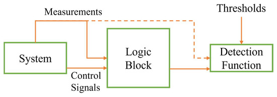
4.1. Logic-Based Methods
The first approach is to use sensor measurements directly with a threshold or constructing logic functions directly from measurements [77–86] which we call logic-based methods. Logic-based methods investigate the relationship between measurements rather than building a model as shown in Figure 6.
These methods require knowledge of circuit operation in healthy mode. In [77,78], the authors exploited the difference in gate capacitances of SiC MOSFET and IGBT for healthy and faulty conditions. Detection of OC and SC faults is possible using only the gate voltage. A similar approach is taken for GaN HEMT devices in [79] where specific and very fast detection hardware is integrated with the gate driver. Any deviation from phase voltage is detected and fault flags are generated. In [80], OC faults in an H-Bridge (HB) were detected and localized. The output voltage of the HB and load current are utilized. The detection method can be scalable for multilevel and three-phase structures. For three-phase PMSM drives, the averaged current technique is used in [81]. By looking into the average phase currents, it is possible to do detection without requiring any system parameters. In [82] OC faults in three-phase inverters are investigated. Phase currents are studied under different fault locations and a 3D trajectory mapping is generated. It allowed for the detection and localization of OC faults for motor drives. In [84], the authors followed a similar mapping to detect multiple OC faults. For multilevel inverters, a modular approach is taken in [83] and detection is done by taking one current and one voltage measurement per H-bridge module. By modifying a regular three-phase inverter by adding an input filter, it is possible to detect OC and SC faults for a three-phase bridge circuit, as shown in [85], as the current trajectory is predictable. In [86], the authors used a single method to detect OC, current, and speed-sensor faults in PMSM drives. They used three-phase current measurements and rotor position. The sum of three current measurements can isolate current sensor faults from OC faults. To increase robustness, the authors used adaptive thresholds and normalized features.
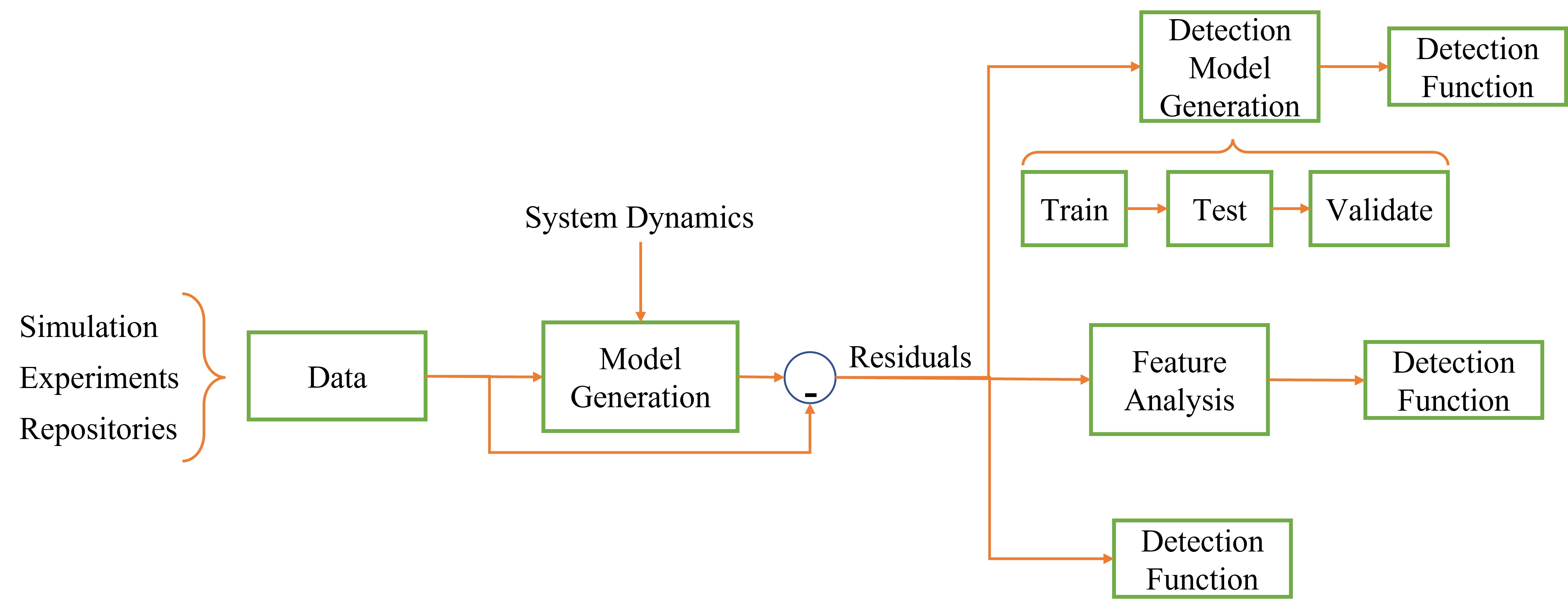
4.2. Residual-Based Methods
The second approach is called residual-based methods and they require a model generated from data or dynamic equations. The source of data can be simulations or experiments. Later, immediate measurements and model output are compared to calculate residuals [87–93]; hence, it is called residual-based methods. The model can be an ML model, a statistical , or a dynamical model. Figure 7 shows the model-based approach in FDD and how residuals can be utilized. A fair amount of papers that use ML can be found in this category, ranging from Bayesian networks to CNNs. As ML methods have an appearance, they are not applied for PE faults as widely as machine faults.
In [87], the authors used Bayesian networks to detect single and double OC faults in PMSM drives. Gate signals and line currents are used from both simulation and experimental data to generate features. For single and double OC faults, 100% and 98.9% accuracies are achieved. In [88], the fuzzy logic method is used with Park’s phase currents. Multiple ML methods, including SVMs, kNNs, and multilayer perceptrons, are compared in [90] for EV inverters.
For multilevel converters, CNN is used in [89] to avoid the feature-extraction process. In the same study, for a four-cell multilevel converter, four voltages and two currents are measured. With less than 100 ms detection time, a 99.7% average fault-detection accuracy is achieved. Since the multilevel converter topology is bidirectional, it is possible to adapt the approach to motor drives. The usage of CNN allowed the detection of faults in varying load conditions. Using the fast Fourier transform algorithm, the proposed method in [91] extracts fault frequency spectrum features, selects the most critical features through a feature selection method, and employs a random vector functional link network to learn the faulty knowledge. The method has been tested and demonstrated high accuracy and robustness in identifying faults, even under varying conditions. In [93], a machine-learning algorithm is used to model the stator current of a single switch using drain current, switch voltage, and temperature. The experimentally validated method shows OC and SC faults can be detected with very high accuracies. For three-phase inverters, the authors in [92] proposed to use residuals from the line and phase voltages to detect OC faults as well as current-sensor faults. To enrich the detection, they also incorporated the polarity of the residuals as features. To calculate residuals, the authors used current measurements from two current sensors instead of three to reduce cost and complexity.
4.3. Controller-Aided Methods
In motor drive applications, the inverter or motor has some form of closed-loop control, which can be a version of field-oriented control, direct torque control, or other control techniques. Other control techniques might employ adaptive or predictive models. In this case, an already-built control model can also be part of FDD.
The third approach is to make use of adaptive or predictive controller architecture within the system for FDD [94–97]. In this approach, estimated states or parameters for control purposes are used for detection as well. This category utilizes estimators and observers present in the controller, as shown in Figure 8.
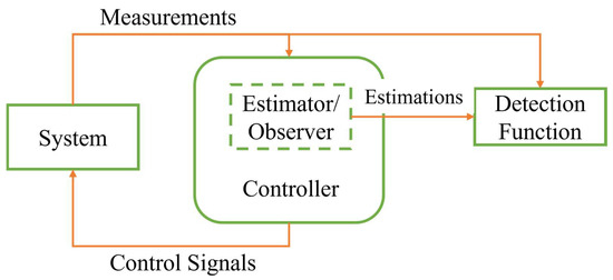
Estimators take previous estimations as a reference to detect anomalies. These methods provide fault-detection capability without requiring additional sensor installations. In [94], a model-based observer is used to estimate the phase currents, and the estimated variables are compared with measurements for three-phase inverters. Similarly, the authors in [95] also use observers but they estimate speed and flux to detect OC failures. For multilevel inverters, model-predictive control is widely used and is also utilized as a fault-detection method as in [96,97].
Table 5. Summary of FDD Methods for Power Electronic Faults.
|
Method |
Topology |
Modulation |
Fault Type |
Switch Type |
Used Signals |
Scalable |
Ref. |
|
Logic Based |
Independent |
Independent |
OC, SC |
IGBT |
Gate voltage |
Yes |
[77] |
|
Logic Based |
Independent |
Independent |
OC, SC |
SiC |
Gate voltage |
Yes |
[78] |
|
Logic Based |
Independent |
Independent |
SC |
GaN HEMT |
Phase voltage |
Yes |
[79] |
|
Logic Based |
H-Bridge Inverter |
LS-SPWM |
OC |
Any |
Output Voltage, load current |
Yes |
[80] |
|
Logic Based |
3-phase Inverter |
SVM PWM |
OC, Current Sensor |
Any |
3-phase currents |
No |
[81] |
|
Logic Based * |
3-phase Inverter |
SPWM–Expandable |
OC |
Any |
3-phase currents |
No |
[82] |
|
Logic Based |
CHB MLI |
SPWM |
OC |
Any |
Current and Voltage Per Leg |
Yes |
[83] |
|
Logic Based |
3-phase Inverter |
SPWM |
OC |
Any |
2 phase currents |
No |
[84] |
|
Logic Based |
Modified 3-phase Inverter |
SVM PWM |
OC SC |
Any |
Input current, gate signals, gate voltage |
No |
[85] |
|
Logic Based * |
3-phase Inverter |
SVM PWM |
OC, Speed, and Current Sensor |
Any |
3-phase current, speed |
No |
[86] |
|
Residual Based |
3-phase Inverter |
SPWM |
OC |
Any |
3-phase currents, Gate signals |
No |
[87] |
|
Residual Based |
3-phase Inverter |
SVM PWM |
OC |
Any |
3-phase currents |
No |
[88] |
|
Residual Based |
MLI |
NA |
OC |
Any |
Module voltage, load current, circulating current |
Yes |
[89] |
|
Residual Based |
3-phase Inverter |
NA |
OC |
Any |
3-phase currents |
No |
[90] |
|
Residual Based |
3-phase Inverter |
Async.-Sync Hybrid Modulation |
OC, Current Sensor |
Any |
3-phase currents |
No |
[91] |
|
Residual Based |
3-phase Inverter |
NA |
OC, Current Sensor |
Any |
3-line voltage, 3-phase voltage |
No |
[92] |
|
Residual Based |
Independent |
Independent |
OC, SC |
Si, SiC MOSFET |
Device voltage, device current, case temperature |
Yes |
[93] |
|
Controller Aided |
3-phase Inverter |
SVM PWM |
OC, Current Sensor |
Any |
3-phase currents |
No |
[94] |
|
Controller Aided |
3-phase Inverter |
SPWM |
OC |
Any |
3-phase voltage, 3-phase current |
No |
[95] |
|
Controller Aided |
MLI |
MPC Based |
OC |
Any |
Module voltage |
Yes |
[96] |
|
Controller Aided |
MLI |
NA |
OC |
Any |
Module input voltage, module current |
Yes |
[97] |
* These methods can also be considered in residual-based methods.
5. Fault Detection and Diagnosis in Sensors
Sensor-fault detection is critical in fault-tolerant drives and the continuation of healthy operation [98–100]. Unexpected sensor measurements confuse the controller as well as existing FDD schemes, indicating a system fault whereas it is a sensor fault. Detecting sensor faults and separating them from system faults is also critical.
In the literature, combined sensor-failure detection schemes with PE faults are reported for motor drive systems [81,86,91,92], as well as standalone detection schemes [98–103].
Combined methods detect and isolate sensor faults from PE faults. In [81], the symmetry of three-phase currents in the drive is exploited. The authors showed that the phase shift between healthy phases changes upon a sensor fault. Similarly, in [86], the summation of phase currents is tracked to determine the sensor fault. A neural network approach is taken in [91], which allowed the detection of voltage and current-sensor faults. FFT-based features are used to detect and diagnose different fault modes of sensors. The authors in [92] worked in systems where only two current sensors are employed and by utilizing phase and line voltage differences.
As for standalone sensor FDD schemes, to detect current sensor faults, in [98], a model-free approach is proposed where the asymmetry between phase-current measurements is used for field-oriented controlled (FOC) drives. Again, for FOC drives [101], researchers used delayed signals to detect current and speed-sensor failures. In [99], the authors proposed multiple estimation schemes. Any discrepancy between estimated values and measured values can be detected and, instead of measured, estimated values are used for fault-tolerant operation. NN-based sensor fault-detection schemes are also proposed in [100,103] and an extreme learning machine is used in [102]for the detection and classification of the type of faults. But, similar to PE faults, due to the lack of available data and the presence of simpler alternatives, ML literature is not as rich in sensor fault detection area.
6. DC Link Capacitor Fault Detection
To detect DC link capacitor failures, its condition should be monitored in real-time. One method to do it is by injecting current or voltage during normal operation as proposed in [104–106]. The injected current or voltage creates a fluctuation in the capacitor power. Monitoring and analyzing this fluctuation allows for real-time ESR monitoring. The authors in [104] injected pulse-type signals whereas, in [105,106], a low-frequency signal is injected. The signal injection has the downside of disturbing normal operation and increasing THD. For this reason, researchers investigated capacitor voltage, capacitor current, and ripple voltage on the DC link capacitor to estimate ESR and capacitance. In [107,108], capacitor current and voltage are used to calculate capacitance directly whereas, in [109], only ripple voltage is used. Extracting ripple voltage requires additional instrumentation and might be challenging if the DC voltage is high. Similarly, in [110], the voltage and current of the DC capacitor are processed using a short-time Fourier transform. Later, ESR and capacity are calculated using mathematical models.
7. Conclusions, Challenges, and Future Work
This paper provided an overview of the faults and relevant FDD methods with emphasis given to recent studies over the past five years. We observed that statistical methods are used to detect all types of machine faults, including bearing, BRB, stator winding, demagnetization, etc. Mathematical analysis, simulations, and simple experiments provide enough information to build these FDD systems. Knowing the fault mechanism and building an FDD around this information still holds its value. Many practical papers are utilizing these mechanisms. A challenge, however, is to use the same or available signals to detect multiple faults. Detecting and diagnosing multiple faults leads to the usage of ML- and DL-based methods.
We can also observe that ML methods are becoming more popular to detect all types of faults but the availability of data is the key. Being able to simulate different operating conditions and various faulty conditions empowers the ML methods. However, the trade-off with the computation time and model complexity is still there to decide on which method to use. Also, it might be misleading to check the success of an ML method simply from its detection accuracy. Readers should be aware that the detection accuracy is decided based on select operating conditions in a given system. When implemented in another system, these algorithms might not produce the same results in terms of accuracy.
In contrast, deep-learning methods require much more data than ML methods and their applications are mostly to detect bearing faults. This is, again, related to the data availability issue. We conclude that there is no clear advantage to using DL methods over ML or statistical methods in terms of accuracy, the number of used signals, and computational cost. The usage of DL methods for FDD on a simple system needs justification but there is room for fault prognosis using DL methods. Also, DL might be useful when information from multiple drives is put together to create a generalized method.
Researchers are exploring condition monitoring for machines and drives extensively. A challenge in condition monitoring is to develop generalizable fault-detection schemes. Many systems might appear to be similar but the difference in the actual products and unique operating conditions make generalization a challenging task. In this sense, time-frequency statistical methods, in general, are tied to fault mechanisms which makes them more generalizable. On the other hand, ML and DL methods rely heavily on data availability and quality; when data is available, they perform exceptionally well. Open-source data repositories for machine drive systems accelerate FDD using ML and DL. As more researchers share their experimental data, the research community will grow and the generalization problem can be tackled. Some open-source experimental data repositories are summarized in Table 5.
As ML and DL are used increasingly, the inherent problems of these methods become apparent in the results. Biased or imbalanced data sets, not having data for unanticipated faults, or multiple types of faults happening concurrently, are such problems. There are also promising methods to overcome these obstacles. Transfer learning and adaptation methods are emerging and showing impressive results [66].
On the power electronics side, device physics is exploited, as well as topology and modulation, to detect faults. As new WBG devices became more common in applications, FDD methods that consider those specific devices should be developed. SiC MOSFETs are becoming more common but GaN HEMTs require more work on their fault detection. Also, as transportation and defense industries are going towards more reliable solutions, paralleling devices have become more popular. This aspect also needs more research.
The abrupt nature of power electronics faults pushed researchers to logic-based methods which are, in general, faster and application specific. Model-based approaches are also fast and can be applied to different scenarios.
Usage of MLIs (cascaded H-bridge or NPC inverters) for drives requires revisiting some established methods. Established methods rely on special properties of generated harmonics in the current and voltage spectra. MLIs produce different current and voltage spectra than those of classical inverters, which is worth investigating.
References
-
- Alshorman, ; Alshorman, A. A review of intelligent methods for condition monitoring and fault diagnosis of stator and rotor faults of induction machines. Int. J. Electr. Comput. Eng. 2021, 11, 2820–2829. https://doi.org/10.11591/ijece.v11i4.pp2820-2829.
- Khan, A.; Asad, B.; Kudelina, K.; Vaimann, T.; Kallaste, A. The Bearing Faults Detection Methods for Electrical Machines—The State of the Art. Energies 2023, 16, 296. https://doi.org/10.3390/en16010296.
- Li, ; Wang, Y.; Wang, J.; Wang, C.; Duan, Y. Recent advances in sensor fault diagnosis: A review. Sens. Actuators A Phys. 2020, 309, 111990. https://doi.org/10.1016/j.sna.2020.111990.
- Kumar, ; Hati, A.S. Review on Machine Learning Algorithm Based Fault Detection in Induction Motors. Arch. Comput. Methods Eng. 2021, 28, 1929–1940. https://doi.org/10.1007/s11831-020-09446-w.
- Gonzalez-Jimenez, ; Del-Olmo, J.; Poza, J.; Garramiola, F.; Sarasola, I. Machine learning-based fault detection and diagnosis of faulty power connections of induction machines. Energies 2021, 14, 4886. https://doi.org/10.3390/en14164886.
- Zhang, ; Zhang, S.; Wang, B.; Habetler, T.G. Deep Learning Algorithms for Bearing Fault Diagnostics—A Comprehensive Review. IEEE Access 2020, 8, 29857–29881. https://doi.org/10.1109/ACCESS.2020.2972859.
- Liang, ; Member, S.; Ali, M.Z.; Member, S. Induction Motors Fault Diagnosis Using Finite Element Method: A Review2020, 56, 1205–1217.
- Liu, ; Bazzi, A.M. A review and comparison of fault detection and diagnosis methods for squirrel-cage induction motors: State of the art. ISA Trans. 2017, 70, 400–409. https://doi.org/10.1016/j.isatra.2017.06.001.
- Xu, ; Qiao, X.; Zhang, N.; Feng, J.; Wang, X. Review of intelligent fault diagnosis for permanent magnet synchronous motors in electric vehicles. Adv. Mech. Eng. 2020, 12, 1–14. https://doi.org/10.1177/1687814020944323.
- He, ; Yang, Q.; Wang, Z. On-line fault diagnosis and fault-tolerant operation of modular multilevel converters—A comprehensive review. CES Trans. Electr. Mach. Syst. 2021, 4, 360–372. https://doi.org/10.30941/cestems.2020.00043.
- Hassan, E.; Amer, M.; Abdelsalam, A.K.; Williams, B.W. Induction motor broken rotor bar fault detection techniques based on fault signature analysis—A review. IET Electr. Power Appl. 2018, 12, 895–907. https://doi.org/10.1049/iet-epa.2018.0054.
- Neupane, ; Seok, J. Bearing fault detection and diagnosis using case western reserve university dataset with deep learning approaches: A review. IEEE Access 2020, 8, 93155–93178. https://doi.org/10.1109/ACCESS.2020.2990528.
- Riera-Guasp, ; Antonino-Daviu, J.A.; Capolino, G.A. Advances in electrical machine, power electronic, and drive condition monitoring and fault detection: State of the art. IEEE Trans. Ind. Electron. 2015, 62, 1746–1759. https://doi.org/10.1109/TIE.2014.2375853.
- Tang, ; Shu, X.; Zhu, G.; Wang, J.; Yang, H. Reliability study of bev powertrain system and its components—A case study. Processes 2021, 9, 762. https://doi.org/10.3390/pr9050762.
- Shu, ; Guo, Y.; Yang, W.; Wei, K.; Zhu, Y.; Zou, H. A Detailed Reliability Study of the Motor System in Pure Electric Vans by the Approach of Fault Tree Analysis. IEEE Access 2020, 8, 5295–5307. https://doi.org/10.1109/ACCESS.2019.2963197.
- Singh, K.; Al Kazzaz SA, S. Induction machine drive condition monitoring and diagnostic research—A survey. Electr. Power Syst. Res. 2003, 64, 145–158. https://doi.org/10.1016/S0378-779600172-4.
- Neupane, ; Kim, Y.; Seok, J. Bearing Fault Detection Using Scalogram and Switchable Normalization-Based CNN (SN-CNN). IEEE Access 2021, 9, 88151–88166. https://doi.org/10.1109/ACCESS.2021.3089698.
- Prieto, D.; Cirrincione, G.; Espinosa, A.G.; Ortega, J.A.; Henao, H. Bearing fault detection by a novel condition-monitoring scheme based on statistical-time features and neural networks. IEEE Trans. Ind. Electron. 2013, 60, 3398–3407. https://doi.org/10.1109/TIE.2012.2219838.
- Immovilli, ; Bellini, A.; Rubini, R.; Tassoni, C. Diagnosis of bearing faults in induction machines by vibration or current signals: A critical comparison. IEEE Trans. Ind. Appl. 2010, 46, 1350–1359. https://doi.org/10.1109/TIA.2010.2049623.
- Elbouchikhi, ; Amirat, Y.; Feld, G.; Benbouzid, M. Generalized likelihood ratio test based approach for stator-fault detection in a PWM inverter-fed induction motor drive. IEEE Trans. Ind. Electron. 2019, 66, 6343–6353. https://doi.org/10.1109/TIE.2018.2875665.
- Siddique, ; Yadava, G.S.; Singh, B. A review of stator fault monitoring techniques of induction motors. IEEE Trans. Energy Convers. 2005, 20, 106–114. https://doi.org/10.1109/TEC.2004.837304.
- Jung, H.; Lee, J.J.; Kwon, B.H. Online diagnosis of induction motors using MCSA. IEEE Trans. Ind. Electron. 2006, 53, 1842–1852. https://doi.org/10.1109/TIE.2006.885131.
- Milkovic, Brief review of motor current signature analysis. HDKBR INFO Mag. 2015, 5, 14–26.
- Toliyat, H.A.; Nandi, S.; Choi, S.; Meshgin-Kelk, H. Electric Machines: Modeling, Condition Monitoring, and Fault Diagnosis; CRC Press: Boca Raton, FL, USA, 2012.
- Chen, ; Zhang, L.; Pattipati, K.; Bazzi, A.M.; Joshi, S.; Dede, E.M. Data-Driven Approach for Fault Prognosis of SiC MOSFETs. IEEE Trans. Power Electron. 2020, 35, 4048–4062. https://doi.org/10.1109/TPEL.2019.2936850.
- Morozumi, ; Yamada, K.; Miyasaka, T.; Sumi, S.; Seki, Y. Reliability of power cycling for IGBT power semiconductor modules. IEEE Trans. Ind. Appl. 2003, 39, 665–671. https://doi.org/10.1109/TIA.2003.810661.
- Franke, ; Zeng, G.; Winkler, T.; Lutz, J. Power cycling reliability results of GaN HEMT devices. In Proceedings of the International Symposium on Power Semiconductor Devices and ICs 2018, Chicago, IL, USA, 13–17 May 2018; pp. 467–470. https://doi.org/10.1109/ISPSD.2018.8393704.
- Meneghini, ; Fabris, E.; Ruzzarin, M.; De Santi, C.; Nomoto, K.; Hu, Z.; Li, W.; Gao, X.; Jena, D.; Xing, H.G.; Sun, M.; Palacios, T.; Meneghesso, G.; Zanoni, E. Degradation Mechanisms of GaN-Based Vertical Devices: A Review. Phys. Status Solidi (A) Appl. Mater. Sci. 2020, 217, 1900750. https://doi.org/10.1002/pssa.201900750.
- Xu, ; Yang, F.; Ugur, E.; Pu, S.; Akin, B. Performance Degradation of GaN HEMTs Under Accelerated Power Cycling Tests. CPSS Trans. Power Electron. Appl. 2018, 3, 269–277. https://doi.org/10.24295/cpsstpea.2018.00027.
- Falck, ; Felgemacher, C.; Rojko, A.; Liserre, M.; Zacharias, P. Reliability of Power Electronic Systems. IEEE Ind. Electron. Mag. 2018, 12, 24–35. https://doi.org/10.1109/MIE.2018.2825481.
- Zhao, ; Davari, P.; Lu, W.; Wang, H.; Blaabjerg, F. An Overview of Condition Monitoring Techniques for Capacitors in DC-Link Applications. IEEE Trans. Power Electron. 2021, 36, 3692–3716. https://doi.org/10.1109/TPEL.2020.3023469.
- Wang, ; Liu, Z.; Lu, G.; Liu, J. Temporal-Spatio Graph Based Spectrum Analysis for Bearing Fault Detection and Diagnosis. IEEE Trans. Ind. Electron. 2021, 68, 2598–2607. https://doi.org/10.1109/TIE.2020.2975499.
- Huang, ; Wen, G.; Dong, S.; Zhou, H.; Lei, Z.; Zhang, Z.; Chen, X. Memory Residual Regression Autoencoder for Bearing Fault Detection. IEEE Trans. Instrum. Meas. 2021, 70, 3515512. https://doi.org/10.1109/TIM.2021.3072131.
- Zarei, ; Tajeddini, M.A.; Karimi, H.R. Vibration analysis for bearing fault detection and classification using an intelligent filter. Mechatronics 2014, 24, 151–157. https://doi.org/10.1016/j.mechatronics.2014.01.003.
- Roy, S.; Dey, S.; Chatterjee, S. Autocorrelation Aided Random Forest Classifier-Based Bearing Fault Detection Framework. IEEE Sens. J. 2020, 20, 10792–10800. https://doi.org/10.1109/JSEN.2020.2995109.
- Zhang, ; Sconyers, C.; Byington, C.; Patrick, R.; Orchard, M.E.; Vachtsevanos, G. A probabilistic fault detection approach: Application to bearing fault detection. IEEE Trans. Ind. Electron. 2011, 58, 2011–2018. https://doi.org/10.1109/TIE.2010.2058072.
- Minhas, S.; Kankar, P.K.; Kumar, N.; Singh, S. Bearing fault detection and recognition methodology based on weighted multiscale entropy approach. Mech. Syst. Signal Process. 2021, 147, 107073. https://doi.org/10.1016/j.ymssp.2020.107073.
- Shen, ; Lu, H.; Sadoughi, M.; Hu, C.; Nemani, V.; Thelen, A.; Webster, K.; Darr, M.; Sidon, J.; Kenny, S. A physics-informed deep learning approach for bearing fault detection. Eng. Appl. Artif. Intell. 2021, 103, 104295. https://doi.org/10.1016/j.engappai.2021.104295.
- Li, ; Yu, Q.; Wang, X.; Zhang, Y. An enhanced rolling bearing fault detection method combining sparse code shrinkage denoising with fast spectral correlation. ISA Trans. 2020, 102, 335–346. https://doi.org/10.1016/j.isatra.2020.02.031.
- Tang, ; Wang, Y.; Huang, Y.; Liu, N.; He, J. Compound Bearing Fault Detection Under Varying Speed Conditions With Virtual Multichannel Signals in Angle Domain. . 2020, 69, 5535–5545.
- Barcelos, S.; Marques Cardoso, A.J. Current-based bearing fault diagnosis using deep learning algorithms. Energies 2021, 14, 2509. https://doi.org/10.3390/en14092509.
- Choudhary, ; Goyal, D.; Letha, S.S. Infrared Thermography-Based Fault Diagnosis of Induction Motor Bearings Using Machine Learning. IEEE Sens. J. 2021, 21, 1727–1734. https://doi.org/10.1109/JSEN.2020.3015868.
- Frosini, ; Harlisca, C.; Szabo, L. Induction machine bearing fault detection by means of statistical processing of the stray flux measurement. IEEE Trans. Ind. Electron. 2015, 62, 1846–1854. https://doi.org/10.1109/TIE.2014.2361115.
- Tang, ; Chen, J.; Dong, K.; Yang, Y.; Lv, H.; Liu, Z. Modeling and evaluation of stator and rotor faults for induction motors. Energies 2019, 13, 133. https://doi.org/10.3390/en13010133.
- Tang, ; Yang, Y.; Chen, J.; Qiu, R.; Liu, Z. Characteristics analysis and measurement of inverter-fed induction motors for stator and rotor fault detection. Energies 2019, 13, 101. https://doi.org/10.3390/en13010101.
- Skowron, ; Orlowska-Kowalska, T.; Wolkiewicz, M.; Kowalski, C.T. Convolutional neural network-based stator current data-driven incipient stator fault diagnosis of inverter-fed induction motor. Energies 2020, 13, 1475. https://doi.org/10.3390/en13061475.
- Lee, T.; Hur, J. Detection technique for stator inter-turn faults in BLDC motors based on third-harmonic components of line currents. IEEE Trans. Ind. Appl. 2017, 53, 143–150. https://doi.org/10.1109/TIA.2016.2614633.
- Cruz SM, ; Cardoso AJ, M. Diagnosis of stator inter-turn short circuits in DTC induction motor drives. IEEE Trans. Ind. Appl. 2004, 40, 1349–1360. https://doi.org/10.1109/TIA.2004.834012.
- Wang, ; Delgado Prieto, M.; Romeral, L.; Chen, Z.; Blaabjerg, F.; Liu, X. Detection of Partial Demagnetization Fault in PMSMs Operating under Nonstationary Conditions. IEEE Trans. Magn. 2016, 52, 3–6. https://doi.org/10.1109/TMAG.2015.2511003.
- Shifat, A.; Hur, J.W. An Effective Stator Fault Diagnosis Framework of BLDC Motor Based on Vibration and Current Signals. IEEE Access 2020, 8, 106968–106981. https://doi.org/10.1109/ACCESS.2020.3000856.
- Akhil Vinayak, ; Anjali Anand, K.; Jagadanand, G. Wavelet-based real-time stator fault detection of inverter-fed induction motor. IET Electr. Power Appl. 2020, 14, 82–90. https://doi.org/10.1049/iet-epa.2019.0273.
- Pietrzak, ; Wolkiewicz, M. On-line detection and classification of pmsm stator winding faults based on stator current symmetrical components analysis and the knn algorithm. Electronics 2021, 10, 1786. https://doi.org/10.3390/electronics10151786.
- Quiroz, C.; Mariun, N.; Mehrjou, M.R.; Izadi, M.; Misron, N.; Mohd Radzi, M.A. Fault detection of broken rotor bar in LS-PMSM using random forests. Meas. J. Int. Meas. Confed. 2018, 116, 273–280. https://doi.org/10.1016/j.measurement.2017.11.004.
- Palacios RH, ; Da Silva, I.N.; Goedtel, A.; Godoy, W.F.; Lopes, T.D. Diagnosis of Stator Faults Severity in Induction Motors Using Two Intelligent Approaches. IEEE Trans. Ind. Inform. 2017, 13, 1681–1691. https://doi.org/10.1109/TII.2017.2696978.
- Singh, ; Naikan VN, A. Detection of half broken rotor bar fault in VFD driven induction motor drive using motor square current MUSIC analysis. Mech. Syst. Signal Process. 2018, 110, 333–348. https://doi.org/10.1016/j.ymssp.2018.03.001.
- Ramu, K.; Raj Irudayaraj, G.C.; Subramani, S.; Subramaniam, U. Broken rotor bar fault detection using Hilbert transform and neural networks applied to direct torque control of induction motor drive. IET Power Electron. 2020, 13, 3328–3338. https://doi.org/10.1049/iet-pel.2019.1543.
- Park, Y.; Yang, C.; Kim, J.; Kim, H.; Bin Lee, S.; Gyftakis, K.N.N.; Panagiotou, P.A.; Kia, S.H.; Capolino, G.-A. Stray flux monitoring for reliable detection of rotor faults under the influence of rotor axial air ducts. IEEE Trans. Ind. Electron. 2019, 66, 7561–7570. https://doi.org/10.1109/TIE.2018.2880670.
- Mirzaeva, ; Saad, K.I. Advanced Diagnosis of Rotor Faults and Eccentricity in Induction Motors Based on Internal Flux Measurement. IEEE Trans. Ind. Appl. 2018, 54, 3961–3970. https://doi.org/10.1109/TIA.2018.2821098.
- Park, Y.; Yang, C.; Bin Lee, S.; Lee, D.-M.; Fernandez, D.; Reigosa, D.; Briz, F. Online detection and classification of rotor and load defects in PMSMs Based on Hall sensor measurements. IEEE Trans. Ind. Appl. 2019, 55, 3803–3812. https://doi.org/10.1109/TIA.2019.2911252.
- Gyftakis, N.; Cardoso AJ, M. Reliable Detection of Stator Interturn Faults of Very Low Severity Level in Induction Motors. IEEE Trans. Ind. Electron. 2021, 68, 3475–3484. https://doi.org/10.1109/TIE.2020.2978710.
- Gurusamy, ; Bostanci, E.; Li, C.; Qi, Y.; Akin, B. A Stray Magnetic Flux-Based Robust Diagnosis Method for Detection and Location of Interturn Short Circuit Fault in PMSM. IEEE Trans. Instrum. Meas. 2021, 70, 3500811. https://doi.org/10.1109/TIM.2020.3013128.
- Goktas, ; Zafarani, M.; Lee, K.W.; Akin, B.; Sculley, T. Comprehensive Analysis of Magnet Defect Fault Monitoring Through Leakage Flux. IEEE Trans. Magn. 2017, 53, 8201010. https://doi.org/10.1109/TMAG.2016.2617318.
- Maraaba, ; Al-Hamouz, Z.; Abido, M. An efficient stator inter-Turn fault diagnosis tool for induction motors. Energies 2018, 11, 653. https://doi.org/10.3390/en11030653.
- Glowacz, ; Glowacz, W.; Glowacz, Z.; Kozik, J. Early fault diagnosis of bearing and stator faults of the single-phase induction motor using acoustic signals. Meas. J. Int. Meas. Confed. 2018, 113, 1–9. https://doi.org/10.1016/j.measurement.2017.08.036.
- Glowacz, Fault diagnosis of single-phase induction motor based on acoustic signals. Mech. Syst. Signal Process. 2019, 117, 65–80. https://doi.org/10.1016/j.ymssp.2018.07.044.
- Toma, N.; Kim, J.M. Article bearing fault classification of induction motors using discrete wavelet transform and ensemble machine learning algorithms. Appl. Sci. 2020, 10, 5251. https://doi.org/10.3390/APP10155251.
- Heydarzadeh, ; Zafarani, M.; Nourani, M.; Akin, B. A Wavelet-Based Fault Diagnosis Approach for Permanent Magnet Synchronous Motors. IEEE Trans. Energy Convers. 2019, 34, 761–772.
- Wen, ; Li, X.; Gao, L.; Zhang, Y. A New Convolutional Neural Network-Based Data-Driven Fault Diagnosis Method. IEEE Trans. Ind. Electron. 2018, 65, 5990–5998. https://doi.org/10.1109/TIE.2017.2774777.
- Mao, ; Liu, Y.; Ding, L.; Li, Y. Imbalanced fault diagnosis of rolling bearing based on generative adversarial network: A comparative study. IEEE Access 2019, 7, 9515–9530. https://doi.org/10.1109/ACCESS.2018.2890693.
- Zhuang, ; Qi, Z.; Duan, K.; Xi, D.; Zhu, Y.; Zhu, H.; Xiong, H.; He, Q. A Comprehensive Survey on Transfer Learning. Proc. IEEE 2021, 109, 43–76. https://doi.org/10.1109/JPROC.2020.3004555.
- Sun, ; Shao, S.; Zhao, R.; Yan, R.; Zhang, X.; Chen, X. A sparse auto-encoder-based deep neural network approach for induction motor faults classification. Meas. J. Int. Meas. Confed. 2016, 89, 171–178. https://doi.org/10.1016/j.measurement.2016.04.007.
- Abid, ; Sallem, M.B.; Braham, A. Robust Interpretable Deep Learning for Intelligent Fault Diagnosis of Induction Motors. IEEE Trans. Instrum. Meas. 2020, 69, 3506–3515. https://doi.org/10.1109/TIM.2019.2932162.
- Case Western Reserve University Bearing Data Center Seeded Fault Test (n.d.). Available online: https://engineering.case.edu/bearingdatacenter ( 24 July 2023).
- Xi’an Jiaotong University—Sumyoung Technology (XJTU-SY) Bearing (n.d.). Available online: https://biaowang.tech/xjtu-sy-bearing-datasets/ (accessed on 24 July 2023).
- Lee, ; Qiu, H.; Yu, G.; Lin, J.; Services, R.T.; Lee, H.; Qiu, G.; Yu, J.L. Bearing Data Set. IMS, University of Cincinnati. 2007. Available online: ( 24 July 2023).
- Repository, P.D. (n.d.). FEMTO Bearing Data Set. Available online: https://www.nasa.gov/content/prognostics-center-of-excellence-data-set-repository ( 24 July 2023).
- Rodríguez-Blanco, A.; Claudio-Sánchez, A.; Theilliol, D.; Vela-Valdés, L.G.; Sibaja-Terán, P.; Hernández-González, L.; Aguayo-Alquicira, J. A failure-detection strategy for IGBT based on gate-voltage behavior applied to a motor drive system. IEEE Trans. Ind. Electron. 2011, 58, 1625–1633. https://doi.org/10.1109/TIE.2010.2098355.
- Climaco-Arvizu, ; Hernández-González, L.; Rodríguez-Blanco, M.A. Fault detection for SiC-Mosfet based on the behavior of gate signal. In Proceedings of the SDEMPED 2015: IEEE 10th International Symposium on Diagnostics for Electrical Machines, Power Electronics and Drives, ;pp. 71–76. https://doi.org/10.1109/DEMPED.2015.7303671.
- Lyu, ; Li, H.; Abdullah, Y.; Wang, K.; Hu, B.; Yang, Z.; Liu, J.; Wang, J.; Liu, L.; Bala, S. A Reliable Ultrafast Short-Circuit Protection Method for E-Mode GaN HEMT. IEEE Trans. Power Electron. 2020, 35, 8926–8933.
- Kumar, Open Circuit Fault Detection and Switch Identification for LS-PWM H-Bridge Inverter. IEEE Trans. Circuits Syst. II Express Briefs 2021, 68, 1363–1367. https://doi.org/10.1109/TCSII.2020.3035241.
- El Khil, K.; Jlassi, I.; Marques Cardoso, A.J.; Estima, J.O.; Mrabet-Bellaaj, N. Diagnosis of Open-Switch and Current Sensor Faults in PMSM Drives through Stator Current Analysis. IEEE Trans. Ind. Appl. 2019, 55, 5925–5937. https://doi.org/10.1109/TIA.2019.2930592.
- Li, ; Cheng, S.; Yu, T.; Wu, X.; Xiang, C.; Bilal, A. An On-Line Multiple Open-Circuit Fault Diagnostic Technique for Railway Vehicle Air-Conditioning Inverters. IEEE Trans. Veh. Technol. 2020, 69, 7026–7039. https://doi.org/10.1109/TVT.2020.2987935.
- Lamb, ; Mirafzal, B. Open-Circuit IGBT Fault Detection and Location Isolation for Cascaded Multilevel Converters. IEEE Trans. Ind. Electron. 2017, 64, 4846–4856. https://doi.org/10.1109/TIE.2017.2674629.
- Trabelsi, ; Boussak, M.; Benbouzid, M. Multiple criteria for high performance real-time diagnostic of single and multiple open-switch faults in ac-motor drives: Application to IGBT-based voltage source inverter. Electr. Power Syst. Res. 2017, 144, 136–149. https://doi.org/10.1016/j.epsr.2016.11.021.
- Farhadi, M.; Fard, M.T.; Abapour, M.; Hagh, M.T. DC-AC Converter-Fed Induction Motor Drive with Fault-Tolerant Capability under Open- and Short-Circuit Switch Failures. IEEE Trans. Power Electron. 2018, 33, 1609–1621. https://doi.org/10.1109/TPEL.2017.2683534.
- Jlassi, ; Cardoso AJ, M. A Single Method for Multiple IGBT, Current, and Speed Sensor Faults Diagnosis in Regenerative PMSM Drives. IEEE J. Emerg. Sel. Top. Power Electron. 2020, 8, 2583–2599. https://doi.org/10.1109/JESTPE.2019.2918062.
- Cai, ; Zhao, Y.; Liu, H.; Xie, M. A Data-Driven Fault Diagnosis Methodology in Three-Phase Inverters for PMSM Drive Systems. IEEE Trans. Power Electron. 2017, 32, 5590–5600. https://doi.org/10.1109/TPEL.2016.2608842.
- Yan, H.; Xu, Y.; Cai, F.; Zhang, H.; Zhao, W.; Gerada, C. PWM-VSI Fault Diagnosis for a PMSM Drive Based on the Fuzzy Logic Approach. IEEE Trans. Power Electron. 2018, 34, 759–768. https://doi.org/10.1109/TPEL.2018.2814615.
- Kiranyaz, ; Gastli, A.; Ben-Brahim, L.; Al-Emadi, N.; Gabbouj, M. Real-Time Fault Detection and Identification for MMC Using 1-D Convolutional Neural Networks. IEEE Trans. Ind. Electron. 2019, 66, 8760–8771. https://doi.org/10.1109/TIE.2018.2833045.
- Moosavi, S.; Kazemi, A.; Akbari, H. A comparison of various open-circuit fault detection methods in the IGBT-based DC/AC inverter used in electric vehicle. Eng. Fail. Anal. 2019, 96, 223–235. https://doi.org/10.1016/j.engfailanal.2018.09.020.
- Gou, ; Xu, Y.; Xia, Y.; Deng, Q.; Ge, X. An Online Data-Driven Method for Simultaneous Diagnosis of IGBT and Current Sensor Fault of Three-Phase PWM Inverter in Induction Motor Drives. IEEE Trans. Power Electron. 2020, 35, 13281–13294. https://doi.org/10.1109/TPEL.2020.2994351.
- Li, ; Wheeler, P.; Watson, A.; Costabeber, A.; Wang, B.; Ren, Y.; Bai, Z.; Ma, H. A Fast Diagnosis Method for Both IGBT Faults and Current Sensor Faults in Grid-Tied Three-Phase Inverters with Two Current Sensors. IEEE Trans. Power Electron. 2020, 35, 5267–5278. https://doi.org/10.1109/TPEL.2019.2946692.
- Yang, ; Gultekin, M.A.; Seferian, V.; Pattipati, K.; Bazzi, A.M.; Palmieri, F.A.N.; Rajamani, R.; Joshi, S.; Farooq, M.; Ukegawa, H. Incipient Residual-Based Anomaly Detection in Power Electronic Devices. IEEE Trans. Power Electron. 2022, 37, 7315–7332. https://doi.org/10.1109/TPEL.2022.3140721.
- Jlassi, ; Estima, J.O.; El Khil, S.K.; Bellaaj, N.M.; Cardoso AJ, M. A Robust Observer-Based Method for IGBTs and Current Sensors Fault Diagnosis in Voltage-Source Inverters of PMSM Drives. IEEE Trans. Ind. Appl. 2017, 53, 2894–2905. https://doi.org/10.1109/TIA.2016.2616398.
- Maamouri, ; Trabelsi, M.; Boussak, M.; M’Sahli, F. Fault Diagnosis and Fault Tolerant Control of a Three-Phase VSI Supplying Sensorless Speed Controlled Induction Motor Drive. Electr. Power Compon. Syst. 2018, 46, 2159–2173. https://doi.org/10.1080/15325008.2018.1534899.
- Zhou, ; Yang, S.; Tang, Y. A Voltage-Based Open-Circuit Fault Detection and Isolation Approach for Modular Multilevel Converters with Model-Predictive Control. IEEE Trans. Power Electron. 2018, 33, 9866–9874. https://doi.org/10.1109/TPEL.2018.2796584.
- Chai, ; Gorla NB, Y.; Panda, S.K. Fault Detection and Localization for Cascaded H-Bridge Multilevel Converter with Model Predictive Control. IEEE Trans. Power Electron. 2020, 35, 10109–10120. https://doi.org/10.1109/TPEL.2020.2978670.
- Salmasi, R. A Self-Healing Induction Motor Drive With Model Free Sensor Tampering and Sensor Fault Detection, Isolation, and Compensation. IEEE Trans. Ind. Electron. 2017, 64, 6105–6115. https://doi.org/10.1109/TIE.2017.2682035.
- Chakraborty, ; Verma, V. Speed and current sensor fault detection and isolation technique for induction motor drive using axes transformation. IEEE Trans. Ind. Electron. 2015, 62, 1943–1954. https://doi.org/10.1109/TIE.2014.2345337.
- Skowron, ; Teler, K.; Adamczyk, M.; Orlowska-Kowalska, T. Classification of Single Current Sensor Failures in Fault-Tolerant Induction Motor Drive Using Neural Network Approach. Energies 2022, 15, 6646. https://doi.org/10.3390/en15186646.
- Tran, D.; Palacky, P.; Kuchar, M.; Brandstetter, P.; Dinh, B.H. Current and Speed Sensor Fault Diagnosis Method Applied to Induction Motor Drive. IEEE Access 2021, 9, 38660–38672. https://doi.org/10.1109/ACCESS.2021.3064016.
- Gou, ; Xu, Y.; Xia, Y.; Wilson, G.; Liu, S. An Intelligent Time-Adaptive Data-Driven Method for Sensor Fault Diagnosis in Induction Motor Drive System. IEEE Trans. Ind. Electron. 2019, 66, 9817–9827. https://doi.org/10.1109/TIE.2018.2880719.
- Dybkowski, ; Klimkowski, K. Artificial neural network application for current sensors fault detection in the vector controlled induction motor drive. Sensors 2019, 19, 571. https://doi.org/10.3390/s19030571.
- Sun, ; Gong, C.; Du, X.; Luo, Q.; Wang, H.; Zhou, L. Online Condition Monitoring for Both IGBT Module and DC-Link Capacitor of Power Converter Based on Short-Circuit Current Simultaneously. IEEE Trans. Ind. Electron. 2017, 64, 3662–3671. https://doi.org/10.1109/TIE.2017.2652372.
- Li, ; Chen, J.; Cong, P.; Dai, X.; Qiu, R.; Liu, Z. Online Condition Monitoring of DC-Link Capacitor for AC/DC/AC PWM Converter. IEEE Trans. Power Electron. 2022, 37, 865–878. https://doi.org/10.1109/TPEL.2021.3092429.
- Abo-Khalil, G.; Al-Qawasmi, A.R.; Eltamaly, A.M.; Yu, B.G. Condition monitoring of dc-link electrolytic capacitors in PWM power converters using OBL method. Sustainability 2020, 12, 3719. https://doi.org/10.3390/su12093719.
- Wechsler, ; Mecrow, B.C.; Atkinson, D.J.; Bennett, J.W.; Benarous, M. Condition monitoring of DC-link capacitors in aerospace drives. IEEE Trans. Ind. Appl. 2012, 48, 1866–1874. https://doi.org/10.1109/TIA.2012.2222333.
- Seferian, ; Bazzi, A.; Hajj, H. Condition Monitoring of DC-link Capacitors in Grid-tied Solar Inverters Using Data-Driven Techniques. In ECCE 2020—IEEE Energy Conversion Congress and Exposition; 2020; pp. 5318–5323. https://doi.org/10.1109/ECCE44975.2020.9235764.
- Sundararajan, ; Sathik MH, M.; Sasongko, F.; Tan, C.S.; Tariq, M.; Simanjorang, R. Online Condition Monitoring System for DC-Link Capacitor in Industrial Power Converters. IEEE Trans. Ind. Appl. 2018, 54, 4775–4785. https://doi.org/10.1109/TIA.2018.2845889.
- Laadjal, ; Sahraoui, M.; Cardoso AJ, M. On-Line Fault Diagnosis of DC-Link Electrolytic Capacitors in Boost Converters Using the STFT Technique. IEEE Trans. Power Electron. 2021, 36, 6303–6312. https://doi.org/10.1109/TPEL.2020.3040499.
This entry is adapted from the peer-reviewed paper 10.3390/en16155602